South Eastern Virginia Rocketry Association

South Eastern Virginia Rocketry Association
JUST GETTING HERE?? The Blogs are out of order...select the dates to the left....

Tuesday, April 28, 2009

ALL FINISHED !!!!

Ok, Jumping ahead from the last set I had to dodge cold fronts and rain storms to get the primer and paint on. Once dried I got it back inside and got the decals on. Now the tough part...checking and rechecking the check list and waiting for Red Glare 6...

Once there we unpacked the set and began going over the parts for damage.

Snap shot...maybe I'll send this one to Smokin' Rockets so they can get one on their web site...

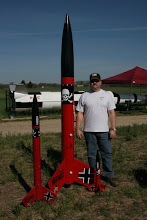
Another shot of the family. I didn't get the Estes one finished in time.

At this point my wife showed up to the field and I was ready to fly.

A little help from my friends

Now we wait for the pads to clear...

Off to the pads....


Listening to two different altimeters is tough...


Loaded up with a LOKI M2550-LB talking with ROCKETS magazine.


First Flame...


Second camera angle...

Third angle....


Alright...after all that my shock cord and parachute tangled up and the MAX came down from 5000' with out any damage...I was ready to pack up and think about Red Glare 7...My buddies said to try it again. With some money changing hands and some pep talks I went to Jeff Taylors tent and bought an M1882-LW...here we go again...
Sunday Morning...going to be the first flight...


At this point I was thinking if I remembered everything...


My second flight was more exciting and successful...thanks to all who helped !!!

Showing off my L3 Temp Card

Monday, March 9, 2009

Ok, the weather has finally warmed up enough I can start laying some filler to get the airframe nice and smooth. I tried a few months ago but the cold air had the epoxy cured in around 3 days....
I had to make a reducer because the kit came with a 98mm motor mount and I will be using a 76mm Loki motor (pictured)

Durning the cold weather I messed around with the recovery gear. Here is the 56" chute (blue)that will be attached to the nose cone and deployment bag (green and yellow) The 15' recovery chute will be attached to the 30' shock cord on the right.

The other end of the shock cord with protector.

This is the drouge end. A 5' chute with 60' of schock cord attached to the fin can

An over all shot.

Ok, now the messy stuff. This will be the first time I had to smooth the airframe with filler. I used West System with 410 filler. This batch was too thin and I layed it on too thick. Once cured it took a couple of days to get it back to the right diameter.

After sanding down with sander then by hand.

I used my aging resin (red) with alot more filler to smooth out the rough areas...


...and start building up the fin fillets.

These will be easier to sand down once cured.
Once I get this smoothed out and how I want around the fins it'll get it's first coat of primer then on to the colors....


Sunday, January 18, 2009

Recovery Gear

With the cold weather coming through southern Virginia I have been placed on hold with anything dealing with epoxy. With that said I decided to look at the recovery gear...

I have 60' of tube nylon that I cut into (3) 20' sections. The two sections closest to the deployment charges I slid a 36" cord protector onto. In the past I had trouble with the loop around the eye bolt burning...

I cut an old cord protector and sewn it at the end of the new one...

Slid the shock cord in with the link...

...and tucked the protector in. Now the whole cord is better protected.


One thing I saw a friend do was to zig-zag the shock cord back and forth to keep the cord organized and prevent tangeling...


He then placed some tape around it to keep it inplace. With a few strategicly placed cuts...the force of the ejection tore the tape but only after it was all thrown clear of the air frame. Test fires in the back yard proved it worked smoothly.


Here was the simple jig I put together.


I also put together a 98-76 reducer.


This is where I had to stop work. I got the airframe coated with epoxy and W-410. I've sanded smooth and have a couple of spots to fill again. My garage isn't heated so I will need to wait till we get out of the 20's to continue...


Here is a run down of my deployment laundry: 36" chute to pull out the Main (attached to the nose cone U-Bolt). Next is the 15' chute inside the deployment bag. Next is 20' of shock cord.


Of course the shock cord will be attached to the forward end of the electronics bay.


On the drouge end I will have 40' of shock cord and a 5' drogue attached at the aft end of the electronics bay.

Monday, September 22, 2008

Electronics Bay completed

Continuing from the last entry of finishing the fin can...

The upper centering ring with U-Bolt

A view from under the upper centering ring.

Applying fillets to the centering rings.

Lower and mid centering.


Using a 4" PVC pipe I cut it in half just above the center line.

Placing the cut PVC on the upper electronics sled. This will be the PML switch bracket.

Drawing out the locations of the switches.

Another view showing the pilot holes.

A dry set up of where the components wil be attached.

A closer look at the switch bracket.

Supports for the PVC bracket.

Bracket in place.

Wood screws to keep bracket in place and epoxy fillets down the side.

The fillets will just be used to keep the PVC from flattening out. I need to be able to take the bracket off incase any of the switches fail.

Both fillets finished and the electronics stand-off pegs glued in.

Electronics sled installed to check clearance.

The layout including wire hold down supports and altimeters installed.

Switches wired and layed out for connections.

Final connections made and wire harness cleaned up.

Jumpers installed to test the electronics.

I need to figure out how to strap down the 12 inches of wires from the ALTS2 Harness...

Friday, August 29, 2008

Fincan and Airframe

After a little research I figures out how to work this...

For full size photos please click the link below.

http://picasaweb.google.com/EricFadely/MyLevel3Journey?authkey=VO3TZlTtQfg


In the past posting I explained that the fins were too heavy and wasn't going to allow me to get all three on at the same time. I drew out a jig on some MDF. I have the fin slots cut out and clamping brackets installed.

The first fin attached and trued up with a square.

The third fin attached...

Epoxy is cures and show for fin can size.

More fillets to support the fiberglass.

A tip I use when applying fiberglass strips is to stick the strips to the fillets with super glue. This will prevent lifting.

Epoxy applied with no lifting.

Another goof up occured when I tried to plug the retainer inserts with wax...epoxy creats enough heat to melt the wax and it begun to ooze out the inserts...I guess the retainer will be put on sooner then expected.

With the fin can curing again I turned my attention to the airframe. First off is making a mandrel.

With the pre-slotted airframe I needed to protect the mandrel disk from epoxy with some wax paper.


I bought Easy-Glas from Giant Leap...easy stuff

Epoxy applied

I also finished the upper air frame too.


The pre-solts were cut at a slight angle so I had to widen them up a little. I'll need to fill that in a little later.

Back on the fin can I aligned the brackets for the upper centering ring...

Installed. I can't epoxy it yet because I will need to get to the middle ring when I epoxy the airframe to the fincan...

Monday, July 28, 2008

Fin Can Part 1

Since I could not get these photos to open up I decided to put larger pictures in it.


Using a 75mm adapter I was able to center my 98mm Aeropack motor retainer. What I hate about the larger retainers is that with the smaller ones you get a 1/4" lip of motor tube to help center the Aeropack. Mine has the motor tube flush with the aft bulkhead which makes it hard to center. With the 75mm adapter in place it was fairly simple. I carefully drilled out dimples where the holes were.


Ready to go to the drill press


Finishing out the holes


Even though there were allen wrench sockets in the inserts I preferred to use the insert T-Wrench I bought a while back.


Inserts........ah.......inserted


Everthing lined up. Thankfully my fins sweep back far enough that the adapter assembly won"t take on any damage when it lands.


The fins were originally cut to support a 75mm motor tube. I will be using a 98mm so I need to trim some of the tab off.


A simple jig set up on my tablesaw sled does the trick


Aligning the 3 fins on the 3 centering rings


Alignment marks on the motor tube


A trick I saw on the Rocket Forum. I hung a weight from the tip of the fin and carefully aligned it till the string matched the fin


My son helping me with the alignment.


Setting up to cure


All three finished...well, almost...

After I got the last fin epoxy tacked and ready to fillet, one of the fins popped loose which threw the whole rig off balance which popped the other two fins off. Come to find out, 2 pound fins don't hold well with just tacking...so...


I drew out a jig which will allow the motor mount to sit on the jig (bolted, actually) and will allow the fins to hang down.
More on the Jig a little later......

The Electronic Sled

I am quickly realizing that developing a blog is almost as much work as building the Max. I have yet to figure out how to post pictures and allow you to open them up into the full size...looks like I'll need to do a little research (if there is anyone out there that is actually reading this, post a comment if you know how to do that)

Back to the project, after getting the electronics bay carcass made I focused my attention on making the sled for the electronics. With three all-thread's to attached to I will use two and maybe use the left over space to put in a camera or video recorder.


I initially decided to use brass tubing to fit over the all-thread but quickly found out that the slightest ding would prevent it from going over the post. I though about using the next size tube but it ended up being too loose and I did not want the sled moving around that much.


My next choice was plastic. Easy to cut, not dent or ding problems.


The placement was a little unprofessional because I had the brass tubes JB Welded earlier but when I accidentally dropped the sled all but one of the brass tubes popped off so the placements were a little out of alignment.


This photo shows the post I will be sliding the sled onto.


Here you can see the misalignment I talked about earlier.


With the plastic tubes in place I wanted to strengthen it up so I layed up some fiberglass. I had to use CA to keep the fiberglass tight around the curves.


Application of my blood red epoxy

Masking tape removed.


Now that my fiberglass has arrived and I have located a 75mm adapter I will begin work on the fin can and airframes...

Friday, July 11, 2008

Let's start with the Altimeter Bay...


I noticed that with 7.5 inch diameter altimeter bay there is sure a lot of room in there. Almost too much. I will only need about a third of it. I need to make sure that this bay can withstand the weight of the entire rocket and then some. I am going to us 3 lenghts of all-thread instead of the normal 2 I use on the 4" rockets. With each of the pieces of all thread 120 degrees apart I can us 2 of them and face my electronics outward. I may use the rest of the space to install a camera or camcorder in the future.
The first lesson I am learning is to slow down. After getting the upper and lower bulkhead done I wanted to coat it in epoxy to keep it from getting burned up with the 4 or 5 grams of BP going off in it. Once I got it coated I put them aside for the night. I came out the next morning and noticed that it hasn't set up at all. I went to the resin and hardener bottle and realized that I needed 3 pumps of hardener instead of the typical West Systems 1 pump. Thankfully my wife talked me into scraping it off instead of just tossing it and buying new bulk plates...sorry Ken. Alright, one day down scraping off all that wasted epoxy...that put a damper on wanting to work on it for about a week. I spent that time trying to figure out how to use Autosketch 9. I love the drawing Vern put out on his web page (http://www.vernk.com/) but he sure does make it look easy...I might get done with the rocket before I figure out how to use the software. Sure wish they came out with a book on it.


Above is the PVC cups I used to hold the black powder charges. My wonderful Home Improvement Centers didn't have the standard 3/4 flat bottom cups so I had to but the ones with holes in the bottoms. A simple epoxy fill fixed that.


To figure out where to put the holes for the all thread I used my old BSD Fin alignment guide.


Marked in 1 inch


This is where the FWD bulk plate T-Nuts will go

I chiseled out a slot for the U-Bolt backer plate because the length of threaded bolt wasn't enough to go through the bulk plate with enough to screw on the nut.


These are the bulk plates. Three one inch holes for the BP charge cups/ignitor pass through, three smaller holes for the all thread and the two in the center is of course for the U-Bolt.


Here the 5/16" T-Nuts to hold the lower plate, so far the BP cups aren't presenting a problem...


Well...here is the problem...when I go to the aft end of the E-Bay I notice that I cannot put the fender washers and wing nuts one because it is too close to the BP cups. Solution? Move the holes over and epoxy fill the old ones


With the holes moved over I I began laying epoxy on the bulk plate...this is where I put the wrong mixture. The photo above was the result of a days scraping and application of good epoxy. Of course the tape is there to keep it from going over the edge. I only layed it up to about 1/8th of an inch to the edge.


Tomorrow... the electronics sled.

Wednesday, July 9, 2008

Let's start the journey...

I thought I would start this by explaning that when I was at NSL 2008 I was amazed by the large projects but my fasination with L3 projects started in November of 2001. Two Canadian's had come down to Whitakers North Carolina to fly their rocket "Draco" I was amazed and hooked right then.

Fast forward to NSL. As I was getting ready to fly my 2nd L2 certification (my original L1 & L2 were taken away because I was overseas past my membership). Everytime I walked by Ken Allens "Performance Hobbies" tent I kept looking at the Smokin' Rockets Der Mega Red Max. Well, enough was enough and I finally bought it. It's 7.5" in diameter and will be about 8-9 feet tall. I am still trying to decide which motor to use. I want the red of the M1550-R from Aerotech or the AMW M1480-RR...but I would love to use the dirty, nasty looking AMW M1730-SK.

For electronics, I already have an older RRC but had to mail it in to be looked at. My 2nd L1 flight it hit pretty hard on the tarmac of Fentress Auxilary Air Field (Home of the South Easter Virginia Rocketry Association). At NSL I had bought an ALTS2 for my second altimeter.


After trying to get onto Smokin'Rockets web page to see if anyone else has put this rocket together I have found that the web site does not work...however I met a guy by the name of Todd Haring that had made one similiar. The only difference is will be that mine has a 24" section of air frame that goes on top the 48" one. (Thanks, Todd, for the picture)


Next...constructing the Altimeter Bay.


Eric